40 electric motor diagram with labels
PDF Understanding Electric Motor Nameplates - Michigan State University The motor with the nameplate of Figure 1 shows the lead connections for operation at 240 volts (low voltage) and at 480 volts (high voltage). Electric motors are rated for operation at such voltages as 115 and 230. These are considered nominal voltages for motors. Electric Motor - Parts of Motor, Working of Electric Motor & Uses - BYJUS Take two bar magnets and keep the poles facing each other with a small space in between. Now, take a small length of a conducting wire and make a loop. Keep this loop in between the space between the magnets such that it is still within the sphere of influence of the magnets. Now for the last bit. Connect the ends of the loop to battery terminals.
Draw a labeled diagram of an electric motor. Explain its principle and ... Working of electric motor: As shown in the diagram, when a current is passed through the coil PQRS the coil starts rotating anti clockwise because a downward force acts on length PQ and at the same time an upward force acts on RS. Therefore, the coil rotates in anti clockwise direction.

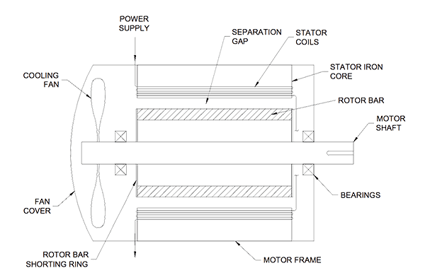
Electric motor diagram with labels
› electric-motor › singleSingle phase capacitor sizing - Electrical Engineering Centre Mar 21, 2011 · The motor itself has 6 wires, brown, black, red, blue, yellow, orange. the motor has 6A labeled. the motor looks like brushless motor. A motor that looks like a drone motor just a bugger version of it. Problem : – No idea how many phases the motor has. faceitsalon.com › emerson-motor-wiring-diagramEmerson Motor Wiring Diagram Gallery - Wiring Diagram Sample Sep 26, 2019 · Name: emerson motor wiring diagram – Emerson Electric Motor Wiring Diagram Kanvamath Org Fan Perfect Psc Emerson Wiring Diagram Electric Motor; File Type: JPG; Source: imovo.co; Size: 162.26 KB; Dimension: 566 x 782 Electric Motor Diagrams - Mr. Electrician's Home Page A Split Phase Capacitor Start Electric Motor may be defined as a form of split-phase motor having a capacitor connected in series with the auxiliary winding. The auxiliary circuit is opened by the centrifugal switch when the motor reaches 70 to 80 percent of synchronous speed. Also known as a capacitor-start, induction-run motor.
Electric motor diagram with labels. Beginner's Guide - How to Read Electrical Schematics - Edrawsoft Here are some of the standard and basic symbols for various components for electrical schematics. 1. Resistors are the fundamental components of electrical schematics. They are usually represented by zig-zag lines with two terminals extending outward. But you can also use the alternate rectangle symbol in the drawing. 2. inspectapedia.com › electric › Electric_MotorElectric Motor Rotation Direction, Which way does an electric ... Purple to yellow = rotate counter-clockwise For an example of electric motor wiring that includes wiring to select electric motor speed options as well as direction of rotation see [live link on the topic page I cited] Dayton Electric Motor Wiring Diagram [PDF], Dayton Electric Mfg. Co., 5959 W. Howard St., Niles IL 60714 USA, retrieved 2017/07 ... 3 draw a labeled diagram of an electric motor explain An electric motor is based on the principle that the current-carrying conductor experiences a force when placed in a magnetic field.The direction of the force is given by Fleming's left-hand rule if the direction of the magnetic field and that of the current are mutually perpendicular. fueleconomy.gov › feg › atv-evWhere the Energy Goes: Electric Cars - Fuel Economy Electric cars use regenerative braking to recover energy typically wasted in braking. When you apply the brakes, the vehicle's inertia turns an electric motor-generator, producing electricity that is then stored in a battery. The electricity can later be used to power the electric motor, which supplies power to the wheels.
› us › enDelta® Ultra- Light 1000, Semi-Electric Bed - Drive Medical The motor is UL approved ; In the event of a power failure, a 9 volt battery, located in the motor, can lower the head and foot sections nine times ; No crank needed ; New and improved hand pendant has large, easy-to-use controls (Figure E) Bed ships in two cartons ; Channel frame construction provides superior strength and reduced weight Motor Connection Diagrams (OLD LECTURE) - YouTube Please use the updated lecture at: Electric Car Diagram | Car Construction Car Anatomy and Repair, Electric car, Engine, How a car Works, Construction. The active reference to source is obligatory if you use materials of a site Car Anatomy 969 shares General Electric Motor Wiring Diagram - Database General Electric Motor Wiring Diagram Source: MUST-KNOW TIPS FOR DIY ELECTRICAL WIRING IN ADDITION TO SWITCHING 1. Have the right tools handy Just like any other DIY job, you want to ensure you have the right tools to do the job.
Electrical Diagrams and Schematics - Inst Tools Types of Electrical Diagrams or Schematics. There are three ways to show electrical circuits. They are wiring, schematic, and pictorial diagrams. The two most commonly used are the wiring diagram and the schematic diagram. The uses of these two types of diagrams are compared in Table 1. The pictorial diagram is usually not found in engineering ... Electric Motor Nameplate Details Explained | Electric Motor ... Electric motors have a rated horsepower (HP) that is determined by the amount of torque they can produce at their running or baseline speed. The nameplate shown in Figure 1 indicates this motor is rated at 1 horsepower. The term "horsepower" comes from the rating of steam engines. Many years ago, James Watt invented the steam engine. PDF Electrical Symbols and Line Diagrams - University of Florida A line (ladder) diagram is a diagram that shows the logic of an electrical circuit or system using standard symbols. A line diagram is used to show the relationship between circuits and their components but not the actual location of the components. Line diagrams provide a fast, easy understanding of the connections and use of components. Electrical Symbols, Electrical Diagram Symbols - ConceptDraw Electrical rotating machines, such as motors and generators, are vital assets for any power plant or large industrial company. An electric motor is an electrical machine that converts electrical energy into mechanical energy. The reverse of this would be the conversion of mechanical energy into electrical energy and is done by an electric generator. In normal motoring mode, most ...
Everything You Need to Know About Wiring Diagram - SmartDraw Pictorial diagrams are often photos with labels or highly-detailed drawings of the physical components. ... Microphone, converts sound into electrical signal; Electrical motor; Transformer, changes AC voltage from high to low or vice versa; Headphone; Thermostat; Electrical outlet;
› Electric-Controller-BrushlessAmazon.com : Electric Motor Controller, 36V/48V 350W ... Suitable for electric bicycles, scooter, etc. Specification: Material: Aluminium alloy Rated Working Voltage: 36/48V Rated Power: 350W Current: 13A Low Voltage Protection: 31/42V Suitable Motor Phrase Angle: 60 / 120 degree Suitable for: electric bicycle, scooter, etc Size: Approx. 9 x 5.3 x 3cm / 3.5 x 2 x 1.18inch Weight: Approx. 204g Package ...
electric motor labeled diagram Car Diagrams Printable. . bmw 1602 electric cutaway cars diagram diagrams ev printable cut ultimate thread technical activee cartype lease recruitment begins process future. Motor dual wiring voltage please help phase plug. Engineering photos,videos and articels (engineering search engine.
electric motor diagram labeled wiring 110 220 machine milling motor diagram need bench help phase Ncert solutions, cbse sample papers and syllabus for class 9 to 12. Electric current science class motor diagram. Motor electric diagram working draw labelled principle explain class rule left hand electrical current through coil its rotating
Draw a labelled circuit diagram of a simple electric motor and explain ... The main parts of electric motor are the magnets, armature, split ring commutators and brushes. The armature consists of a rectangular coil made of insulated copper wire wound on a soft iron core. The coil is mounted on an axle and is placed between the cylindrical concave poles of a magnet.
Electric motor Diagram | Quizlet The commutator is a broad ring of metal mounted on the axle at one end of the armature, and cut into an even number of separate bars (2 in a simple motor). Each opposite pairs of bars is connected to one set of coils.
How to Read an Industrial Pump Motor Wiring Diagram Each motor has several wires in it which are labeled with letters and numbers. For "Line", take the wires the diagram instructs, wrap them together, and connect them to the incoming voltage. For "INSUL", take the wires, wrap them together, and twist them into an insulated cap. Once this is done, the motor is ready to be turned on.
Single Phase Electric Motor Wiring Tutorial: Baldor, WEG, Leeson In this video, Jamie shows you how to read a wiring diagram and the basics of hooking up an electric air compressor motor. These tips can be used on most ele...
Question 11 Draw a labelled diagram of an electric motor. Explain its ... Principle: It works on the principle of the magnetic effect of current. A current-carrying coil rotates in a magnetic field. Working: When a current is allowed to flow through the coil MNST by closing the switch, the coil starts rotating anti-clockwise. This happens because a downward force acts on length MN and at the same time, an upward force acts on length ST.
Electric Motor Diagram Illustrations, Royalty-Free Vector Graphics ... Browse 983 electric motor diagram stock illustrations and vector graphics available royalty-free, or start a new search to explore more great stock images and vector art. Newest results Direct current generator Generator info graphic for science education. Illustration. Engineering backgrounds. Mechanical engineering drawing
electric motor diagram wiring diagram pump waterway 56 executive spa pf motor gecko pumps speed xp2 emerson tub xp2e frame parts aqua 230v Without Joint Connection Three Phase Electric Motor All In Winding phase motor winding three connection electric Draw A Labelled Diagram Of Electric Motor - PURSUE-AROUNDME pursue-aroundme.blogspot.com

7. Draw a neat labelled diagram of Electric motor. Mention the principle of an electricmotor ...
What is an Electric Motor? with the Help of a Labelled Diagram ... In an electric motor, a rectangular coil ABCD in placed between two magnets in poles N and S. Now, current is passed through it continuously. When current is passed into the coil, it produces a magnetic field around it. The two magnetic fields interact and cause the coil to rotate. When the coil rotates, the shaft attached to it also rotates.

Patent US8269448 - Methods and systems for recording operating information of an electric motor ...
Electric Motor Diagram Stock Illustrations - 780 Electric Motor Diagram ... Download 780 Electric Motor Diagram Stock Illustrations, Vectors & Clipart for FREE or amazingly low rates! New users enjoy 60% OFF. 191,511,643 stock photos online. ... Types of electric vehicles with labeled battery and motor outline diagram. Educational scheme with hybrid, plug-in and electricity car power supply vector ...

the picture shows a basic diagram of an electric motor. which labels best complete the diagram ...
Electric Motor - Principle, Working, Diagram - Explained step by step (a) An electric motor converts mechanical energy into electrical energy. View Answer NCERT Question 11 - Draw a labelled diagram of an electric motor. Explain its principle and working. What is the function of a split ring in an electric motor? View Answer NCERT Question 12 - Name some devices in which electric motors are used. View Answer
› worksheets › ac-motorAC Motor Control Circuits Worksheet - AC Electric Circuits After the motor has had time to speed up, another set of “starter” contacts bypass line power around the resistors, directly to the motor windings. Draw a diagram showing how this could be done for a single-phase electric motor, using two starter contacts: “R” for “run” and “S” for “start”.
Electric Motor Wiring Diagram 220 to 110 Sample Name: electric motor wiring diagram 220 to 110 - Electric Fan Wiring Diagram With Capacitor Save Capacitor Start Electric Motor Wiring Diagram Fresh For Best Single. File Type: JPG. Source: wheathill.co. Size: 1.27 MB. Dimension: 3229 x 2480.
Motor Connection Diagrams - Electric Motor Warehouse Single Phase Terminal Markings Identified By Color: (NEMA Standards) 1-Blue 5-Black P1-No color assigned. 2-White 6-No color assigned P2-Brown. 3-Orange 7-No color assigned. 4-Yellow 8-Red. Three Phase Connections: Part Winding Start: 6 Leads NEMA Nomenclature: WYE or Delta Connected.

The figure below shows a simple electric motor. Study the figure and answer the questions that ...
Electric Motor Diagrams - Mr. Electrician's Home Page A Split Phase Capacitor Start Electric Motor may be defined as a form of split-phase motor having a capacitor connected in series with the auxiliary winding. The auxiliary circuit is opened by the centrifugal switch when the motor reaches 70 to 80 percent of synchronous speed. Also known as a capacitor-start, induction-run motor.


Post a Comment for "40 electric motor diagram with labels"